- Published on
Remotely Controlled Lawn Tractor
History
A quick look back at the project's origin, its progression, technology choices, and issues that plagued the first iteration of the project.
Unfortunately, I didn't document the progress of the project as I was building it. I started throwing ideas around for the project back in 2016 and some details and how I arrived at some of the design decisions escape me now. But, most of the important work is very recent so all the detail is here.
How it all started
I have a large and grassy yard and after mowing it for what seemed like countless hours every year I wanted to make my life a bit easier. Initially, I wanted to build a remotely controlled lawn tractor using an RC flight controller. The idea seemed to be relatively simple and quick to implement, but this approach was done many times before so I wanted to do something different.
From the mechanical engineering standpoint, the project would still be challenging but where I wanted to do things differently than other projects was on the software and hardware side. I wanted this to be more of a drone experience with real-time video streams, controls, and telemetry.
First steps
I started with a basic proof-of-concept harness. I wired up a couple of DC motors to a motor controller and an RC transmitter. With the RC controller, I was able to drive the motors backward and forward. Since the motor controller (BasicMicro's RoboClaw) supports RC mode, it was an easy and simple way to kick things off.
Wires and bits of software everywhere
When I started to piece it all together, all the components and breadboards were all over my workspace. GPS and the absolute orientation module were connected to PJRC's Teensy MCU (Microcontroller Unit - version 3.5). The Teensy 3.5, Xbox controller and two USB camera modules were connected to a USB hub and the hub was plugged into my laptop.
On the software side, I considered a desktop app to host the video feed and show sensor data visualizations. But the web app seemed more appropriate for the use case. It was more challenging and would allow me to remotely control the tractor from any device with a browser. I had to rethink the implementation of a lot of functionality and introduce new tooling.
In my first draft of the app, I started to develop web components in Vue.js. After writing code for several days, this is what I had:
- HUD (heads-up display) gauges - using Canvas Gauges
- Google Maps - with red tractor marker and GPS data fed to it from a Ublox NEO-7 module
- Depiction of wheels and throttle position - drawn with Paper.js
- Video from a USB camera module, using MJPEG stream, displayed as a background layer in the browser
The server-side code responsible for communication between the MCU and the browser was done in Node.js.
So close yet so far
Next, it was time to move away from breadboards and build a standalone tractor control enclosure. The enclosure would house all the electronics that needed to be mounted on the mower. For an onboard SBC (Single Board Computer), I went with the Raspberry Pi 3B due to its relatively low power consumption. In the meantime, I added another Teensy (3.2) to be a dedicated MCU for critical functions such as throttle and steering. The existing Teensy 3.5 would be used to aggregate telemetry data from various sensors.
At this point, all USB ports on the Raspberry PI 3 (RPi3) are in use with two USB camera modules and two Teensy MCUs. The system was taking shape but unfortunately, there were several problems:
- At first, I noticed that MJPEG streams started dropping frames; they were no longer low latency and after a minute or so would freeze completely.
- The Node.js code that handled communication with MCUs was not designed to connect to multiple Teensys. It was connecting to one or the other but it wouldn't connect to both.
- The web code became bloated and unnecessarily complex making adding features cumbersome.
The problems were a bit discouraging since there was no simple workaround to any of them. At that point, I decided to step back and focus on other things. It was not clear to me at that time if I would ever come back to finish it.
Getting back to it
Deep dive into the design of individual parts that make up the current iteration of the system. I describe how the components are interconnected and my struggles to make sure the setup is performing optimally.
After an extended break from the project, in mid-2019, I decided to take a fresh look at what I've built so far. The problems I listed in the previous section meant that I had to start pretty much from scratch when it came to software and most of the firmware code.
Most importantly, I decided to throw out the biggest initial project requirement. I was no longer interested in building a remotely controlled mower. I decided to focus on building a platform that can be further enhanced with, for example, self-driving capability.
With the experience I now had and all the components selected, I had a very clear picture of what to do next. I decided to approach the project in three distinct stages:
- Software - web UI dashboard and middleware Node.js app to drive MCUs. This work also included firmware code for both MCUs.
- Hardware - tractor WiFi connectivity, cameras, sensors, motor controller, and all electrical connections.
- Mechanical - steering and throttle motors, limit sensors, and quadrature encoders. Also included different parts I fabricated to mount many of the components listed here.
Software
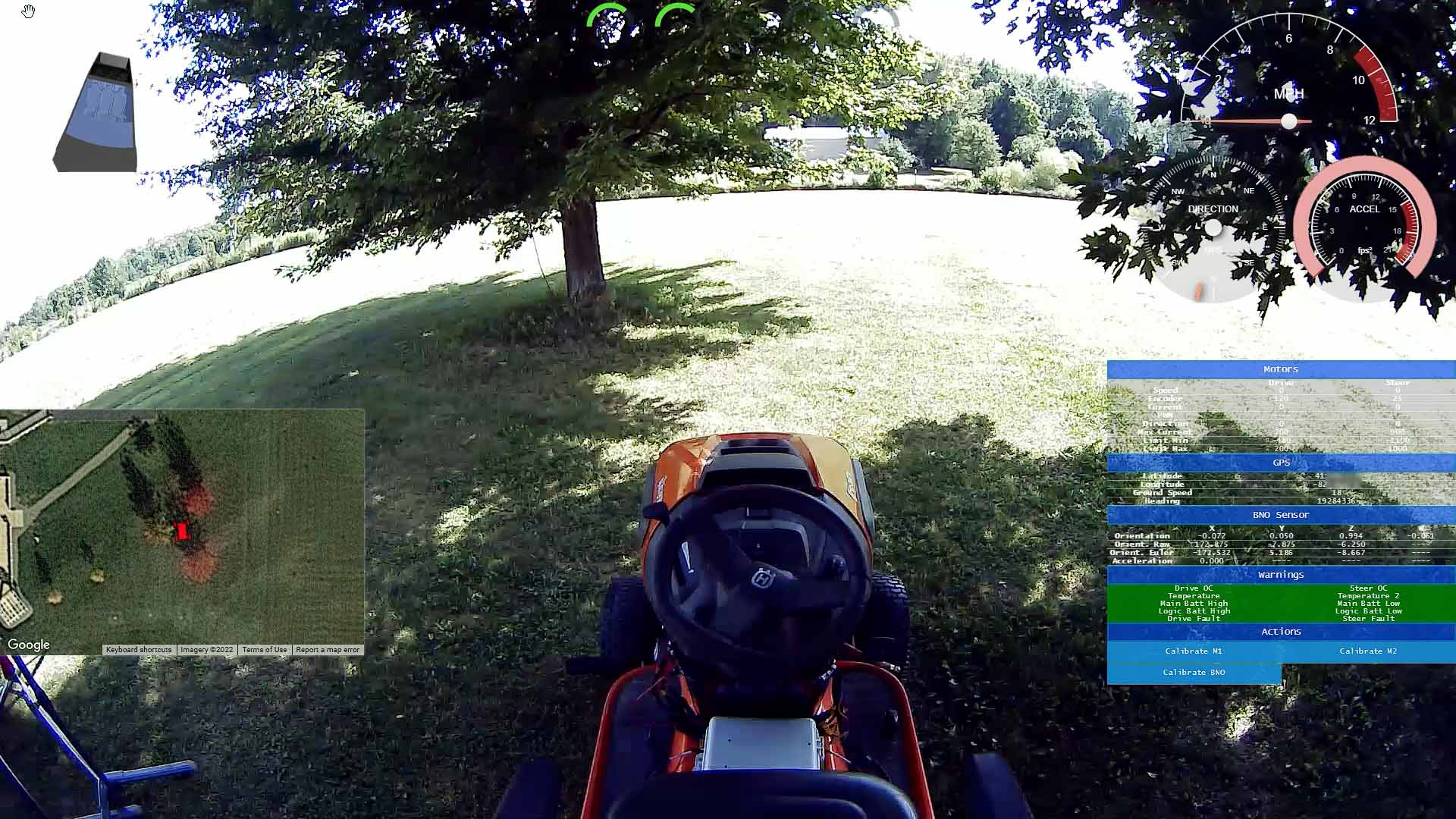
Web UI - I decided to go simple - JavaScript ES2018 and Browserify for module management. Most of the code needed to be rewritten and some of it redesigned. The app was divided into the following components:
- IMU visualization - data coming from BNO055 was visualized as a Tesla truck rendered using three.js.
- Map - data from the GPS module is sent to Google Maps API. The tractor is represented by a red vehicle marker in the center of the map.
- HUD gauges - to visualize speed, compass, and acceleration data, the HTML Canvas Gauges project was used. The data for the gauges comes from GPS and BNO055 modules.
- Voltage and Current gauges - the extra visualization of the current drawn by the two motors. Also, I added gauges for the voltages measured at the motor controller.
- Telemetry pane - representation of raw data coming from BNO055, GPS, and motor controller.
- Debug pane (not pictured) - aggregates log messages coming from MCUs and Node.js app.
All pieces of data coming in and out of the browser are transmitted via the WebSocket.
Other software components:
- Augmented Reality - even if the implementation of AR is rudimentary, I felt the platform's potential needed to be shown off. Since I had access to the GPS and orientation sensors, it did not take much to add one extra feature.
Location-based Augmented Reality support was added with AR.js. I placed Articuno (the large blue bird) at a specific location in the real world. Using the library, the GPS coordinates of the tractor combined with the orientation sensor allowed me to get close to the object and eventually pass it.
The AR.js uses the browser'snavigator.geolocationto access GPS location. This property had to be overwritten to allow the use of GPS data from the tractor as opposed to data from the device on which the browser runs. Similarly, the browser's orientation events are based on orientation data coming from the IMU mounted on the tractor. - Video Streams - I needed two stable, low latency 1080p/30fps streams that didn't consume the entire bandwidth of the RPi3. One way to achieve that inexpensively was to use camera modules that supported H.264 compression. After trying out several different streaming technologies I chose WebRTC because of its low latency capabilities. Running a WebRTC client on RPi3 was out of the question. RPi3 is just not powerful enough. The idea was to wrap each of the two H.264 streams, from both cameras, in an RTSP layer (using ffmpeg) and send them out to an RTSP server from where the streams would be picked up by the WebRTC client. The WebRTC client app and the RTSP server would live on a ground station - Raspberry PI 4 (RPi4).
- Gamepad - The Gamepad API exposed by browsers allowed me to read the controller axis and buttons. As soon as the value was read, it was sent via the WebSocket to RPi4 and from there broadcasted to RPi3 on the tractor, and finally to the dedicated MCU via USB Raw HID.
- Teensy MCUs - Both MCUs are connected to RPi3 via USB. There are two communication channels in use, USB Raw HID and Serial.
- USB Raw HID - it is used for transmission of telemetry and steering/throttle data.
Essentially, it is used for anything that needs to be received/sent in near real-time. Each Raw HID packet could contain 64 bytes of data which may not seem like a lot but it is enough to send pretty much the entire state of the gamepad or most of the telemetry data coming from the mower in just a few packets. Up to 1000 packets can be sent/received per second allowing for near real-time communication between MCUs and RPi3. - USB Serial - serial communication is used to stream log data into the UI debug component. Also, log data from the MCUs is shown in the stdout of the Node.js app container running on RPi3. This allows for easier debugging of the firmware code.
- USB Raw HID - it is used for transmission of telemetry and steering/throttle data.
- The RPi3 is installed on the tractor, and runs:
- two instances of ffmpeg configured to forward front and back RTSP camera streams to the ground station (RPi4).
- A Node.js app that interacts with the two Teensy MCUs. It is also responsible for processing input from the Web UI app. All software is containerized using Docker.
Hardware
Overview
The enclosure that houses all the electronic components is roughly 11x11 in. It is mounted on the floor of the tractor between the seat and steering column. It is held up by four vibration-damping sandwich mounts.
There are four layers inside the box starting from the bottom:
Power Distribution Layer
The tractor battery is connected to two buck converters (12VDC and 5VDC) and directly to the motor controller. The 12VDC converter provides regulated power to the WiFi router and the 5VDC converter powers the RPi3 and the cooling fan. The MCUs and external sensors are powered by a 5VDC regulated source on the motor controller.

Networking Layer
After some research, I decided to go with the Asus RT-AC1200 V2 router due to the small factor, 12VDC power input, price, and ability to easily detach existing antennas from the board. The router's ethernet ports are only 100 Mbps but this is not an issue since RPi3 can't push data faster and higher speeds are just not needed.

Telemetry and SBC Layer
It contains SBC (RPi3), motor controller, GPS, and IMU modules:
- Motor controller - RoboClaw V5 (15A version). Connected via Serial to Teensy 3.2, is responsible for throttle and steering controls. It's a very capable and feature-rich motor controller that saved me a lot of time when troubleshooting issues.
- GPS - the NEO-M9N module is connected to Teensy 3.5 via Serial. It provides location, heading, and speed data.
- BNO055 module - this 9 Degrees of Freedom sensor is connected via I2C to Teensy 3.5. It provides the acceleration, orientation, and rotation data.
- RPi3 - runs software that interfaces with the MCUs and creates two RTSP camera streams. RPi3 connects to the WiFi router via ethernet cable for external communication. Even though USB and Ethernet ports share bandwidth on RPi3, the whole system moves around 48 Mbps of data which is within the RPi3's practical limits.

MCUs and External Sensor Connectors Layer
Both MCUs and connectors to external sensors are mounted on a protoboard. Two quadrature encoders and six hall effect sensors for throttle and steering are attached to the connectors on this layer.
There are two Teensy MCUs configured for different tasks. Teensy 3.2 is responsible for drive and throttle control whereas Teensy 3.5 collects and processes telemetry data. Both Teensys are connected to an RPi3 via USB.

External Components
Cameras and WiFi antennas mount
Both cameras and four WiFi antennas (two 2.4Ghz and two 5Ghz) are mounted behind the tractor seat on two 5ft L-shaped aluminum corner angle bars. The bars are attached to the mower with vibration-dampening washers.
The 170-degree angle fisheye camera is facing forward. The camera facing backward has approximately 110 degrees viewing angle. The camera modules are housed in off-the-shelf enclosures that I had to slightly modify for fitment. I ended up removing the clear plastic covers for a better quality image.


Xbox controller
I used a wired Xbox 360 controller for testing. Any gamepad/steering wheel could be used as long as it is supported by the browser's implementation of the Gamepad API and preferably uses standard button mapping.
Ground station (RPi4)
The RPi4 hosts the web UI app, Nginx reverse proxy, RTSP server, and WebRTC client. Similarly to RPi3, all software is containerized. RPi4 also bridges the tractor network with the house network. A USB3 wireless AC1200 adapter connects the RPi4 to the WiFi router on the tractor.

Mechanical
To be able to use the tractor for the project, several mechanical and structural modifications had to be made to it. On top of that, the tractor is 9 years old and multiple parts were worn out and had to be replaced or fixed.
I wanted to hide all the project-related mechanical components inside the body of the tractor. I started by disassembling the steering column and its supports so I could first focus on the throttle mechanism located closest to the frame.
Throttle
I removed the parking brake and "cruise control" linkages entirely. This freed up plenty of space inside (lower dash) to start experimenting with the throttle assembly design.
I went with an approach of mounting a right-angle motor horizontally and attaching a round disk to its shaft. The disk pushes a lever attached to the throttle linkage. It is a simple angular to linear motion conversion.

There are three hall effect sensors attached to the disk working as limit switches (forward, center, backward). The neodymium rare earth magnet attached to the lever activates the switches at the limit positions.
Right above the motor, I mounted a quadrature encoder to measure how far, in pulses, the lever would move. The encoder is connected to the motor shaft via the #35 chain.
Quadrature Encoders
The quadrature encoders allowed me to very precisely control both the throttle and steering movement. The values from analog gamepad sticks and paddles were translated to encoder values. Then, those values were used to turn the motor to the desired position.
The distance, in pulses, between the Hall effect sensors (limit switches) had to be measured the first time the tractor was ready to be driven. Those one-time encoder calibration values were saved and reused each time the tractor was started up.
Transmission work
A problem became apparent very quickly. Too much power was required to overcome the spring tension inside the mower's hydrostatic transmission. The spring is responsible for keeping the throttle pedal in a neutral position when not depressed.
Unfortunately, I had to disassemble and “fix” the perfectly working transmission.
After draining all the fluids, I removed an internal cover and a couple of pumps to get to the spring.

I decided to fabricate my own spring. I purchased several springs and began to shape them on a vise. It took me several tries before I found a good combination of stiffness and shape.

After installing the new spring, it was now easy for the motor to move the throttle pedal.
Steering
It took some time before I found an optimal location for all the parts related to steering control. In the end, I mounted a right-angle motor under the tractor's crossmember.
I used the same type of motor as for the throttle. Using the same motor type turned out to be a mistake but more on that later.
The 4" shaft of the motor was protruding on the upper side of the crossmember where I mounted a ~2" sprocket. The sprocket is connected, via a #35 chain, to a ~3.5" sprocket on the steering shaft.
The quadrature encoder was mounted on top of the crossmember and connected to another ~2" sprocket on the steering shaft.
The hall effect sensors were mounted on the surface of the crossmember. A neodymium rare-earth magnet was attached under the ~3.5" steering shaft sprocket, activating the sensors whenever limits were reached.

This setup worked under test conditions pretty well but it was very difficult for the motor to turn the wheels without drawing a considerable amount of current. This caused the motor to start overheating. It wasn't designed for continuous duty.
At this point, I was committed to using the motor so to deal with this problem, I first started replacing and/or fixing worn-out parts related to steering to eliminate as much friction between parts as possible.
Steering assembly work
First, I replaced both left and right spindle assemblies to deal with a major tire toe-out. Spindle replacement helped improve the toe-out problem a lot. Then, I noticed the front axle was pretty wobbly. It would have had to be replaced but a new one was around $100 so I decided to just flip it around. That worked great and now the tires were mostly straight. Finally, to make steering even smoother, I installed what's dubbed a "poor man's power steering". It is a roller bearing with a washer on each side of the bearing installed between the spindle and the axle.
Firmware improvements
There was one more major problem to overcome. I noticed that even if the motor was idling, it was consuming a lot of power. It varied wildly, anywhere from 1-2 amps to the maximum allowed. No amount of adjusting PID coefficients helped the situation. I finally chucked it up to the motor type, since the behavior was similar when driving it with a PWM signal.
The constant current flowing through the motor added to the overheating issue. The fix was to set the motor duty to zero when the motor was idle or at a constant position. This applied to situations in which, for example, the throttle pedal was all the way up/down or when the tractor was driving in a straight line. Any values from the gamepad to initiate motor movement would override this behavior and current would be applied to the motor.
Safety Bypass and Kill Switch
Tractor mowers have several safety features and they have them for a very good reason. For my purpose, most of them had to be disabled, or else the tractor would not even start without a human operator.
- Brake switch - to start the tractor a person needs to depress the brake pedal while turning on the engine.
- Seat switch - it engages when a person occupies the driver's seat. The person needs to remain seated while the tractor is operational. If the switch is not depressed, the engine turns off. Disabling the safety features on a tractor with the mower deck removed is not as risky but still, a runaway situation could occur. To manage this I added a kill switch.
A kill switch is a simple device I built that consists of an RC switch with a relay, an RC receiver, and a battery pack to power the device.

The red positive wire coming out of the solenoid and going into the ignition is split in two and connected to Common and Normally Closed contacts on the SPDT switch. Using the RC controller, I can activate the relay, switching the contact to Normally Open causing the engine to shut off.
By making the kill switch's channel of communication independent of the rest of the system, I now have a reliable way to prevent a potentially dangerous situation.
In the end
This was a very challenging and fun project to work on. Writing the software and fabricating all the parts taught me many engineering and system design lessons. There is still plenty that can be improved upon but I had to stop somewhere. I hope you enjoyed reading about it as much as I enjoyed creating it.